
The idea of the project is to provide the ability to place your Nextion display and hotspot in different locations in your house. Since UART (Universal Asynchronous Receiver/Transmitter) protocol is used for communication between the hotspot and display, it becomes easier to experiment with all kinds of options.
There are many controllers available today with UART interface onboard. Some of them can even emulate virtual COM ports when they are connected via USB. In this project we will be using ESP32 controller.
Possible solutions for this project include:
- two ESP32 controllers required. First controller connected to the hotspot modem port. Second controller connected to Nextion display. Nice option is that they can even live in their own isolated WiFi network. No Access Point needed. One of the controllers can work in AP mode. Easy to implement, maintain and troubleshoot.
- only one ESP32 controller required. It will be connected to Nextion display using UART and connected to your home WiFi network using wireless interface. There will be a program which runs on hotspot, emulates a virtual COM port and interacts with display ESP32 controller via hotspot network interface. This approach requires advanced knowledge of Linux systems and troubleshooting might be also challenging
I’m following first approach because:
- it’s secure – it’s in isolated network which doesn’t use your home WiFi
- it’s easy to troubleshoot – you can enable debug info and see how hotspot and display are talking to each other
- it’s easy to maintain – since it’s a separate modules you can just disconnect them and connect display directly to hotspot. No re-configuration or any additional steps needed.
Approach
ESP32 is a lightweight, low-powered controller which already has all necessary interfaces. No additional elements needed.
Pitfalls/warnings/considerations:
- ESP8266 or ESP32 can be used without any code changes. Even wiring will be the same with most of the modules
- Do not use the EPS32 USB emulated COM port – during boot process it sends debug information into this port. From time to time this data drives the Nextion display crazy!
- Triple check the EPS32 pinout! I’ve seen at least 3 variations. Even text markers near pins might be wrong
- Do not power Nextion display from 5v ESP32 pin and ESP32 via micro-USB. There might be visible backlight noise on display.
- Do not touch pins when you are debugging. Touching the UART pins will generate some garbage data which might stick hotspot or display
- Highspeed Nextion driver hasn’t been checked
- Setup and configure your display with direct wire connection. Switch to ESP32 modules only after everything is configured and is working properly
Basic setup requires:
- 2pcs ESP32 (ESP8266) board
- USB <> micro-USB cable
- Arduino IDE
- wires
The hotspot side
The first board needs to be connected to the hotspot modem port and act as a WiFi Access Point. It will have web server on it and will wait for incoming connections. After the connection is established it will send data from UART to the other side and push data received from the other side in UART.
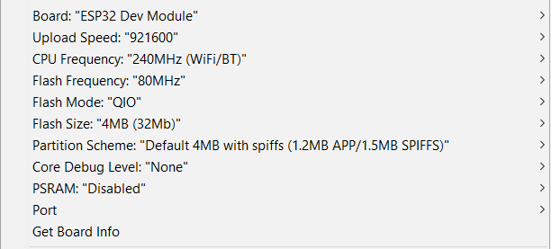
The board first needs to be connected to PC for programming. Appropriate parameters should be set in Arduino to interact with the board (my board configuration provided on a screenshot).
The following code should be placed in Arduino IDE:
(ssid and password should be changed to something unique and long enough)
#include <WiFi.h>

// debug log, set to 1 to enable
#define ENABLE_DEBUG_LOG 0

// wifi config
const char* ssid     = "espwifinetwork";
const char* password = "hdnHsncjdf7hs763Hbfjhse3A";
const int channel = 8;

// ethernet config
const IPAddress local_IP(192, 168, 4, 1);
const IPAddress gateway(192, 168, 4, 1);
const IPAddress subnet(255, 255, 255, 0);

// rs-server config
const int serverPort = 1234;

// rs port config
const int baudrate = 9600;
const int rs_config = SERIAL_8N1;

// reading buffor config
#define BUFFER_SIZE 1024

// global objects
WiFiServer server;
byte buff[BUFFER_SIZE];
int size;

void debug_log(char* str) {
#if ENABLE_DEBUG_LOG == 1
   Serial.println(str);
#endif
}

void setup() {
#if ENABLE_DEBUG_LOG == 1
   Serial.begin(115200, rs_config);
#endif

// init rs port
   Serial2.begin(baudrate, rs_config);

// init wifi connection
debug_log("WiFi initialisation...");

WiFi.softAPConfig(local_IP, gateway, subnet);
WiFi.softAP(ssid, password, channel);

#if ENABLE_DEBUG_LOG == 1
   Serial.println("connected to WiFi");
   Serial.println("IP adddr: ");
   Serial.println(WiFi.softAPIP());
#endif
   delay(1000);

//start server
   server = WiFiServer(serverPort);
   server.begin();
   delay(1000);
   debug_log("server started");
}

void loop() {
// wait for client
   WiFiClient client = server.available();
if (!client)
return;

debug_log("client found");

while (client.connected()) {

  // read data from wifi client and send to serial
  if (client.available()) {
             size = client.available();
             size = (size >= BUFFER_SIZE ? BUFFER_SIZE : size);
             client.read(buff, size);
             Serial2.write(buff, size);
             Serial2.flush();
             #if ENABLE_DEBUG_LOG == 1
                Serial.println("WiFi->Serial");
             #endif
            }

  // read data from serial and send to wifi client
  if (Serial2.available()) {
             size = Serial2.available();
             size = (size >= BUFFER_SIZE ? BUFFER_SIZE : size);
             Serial2.readBytes(buff, size);
             client.write(buff, size);
             client.flush();
             #if ENABLE_DEBUG_LOG == 1
                Serial.println("Serial->WiFi");
             #endif
            }
}
   debug_log("client disconnected");
   client.stop();
}
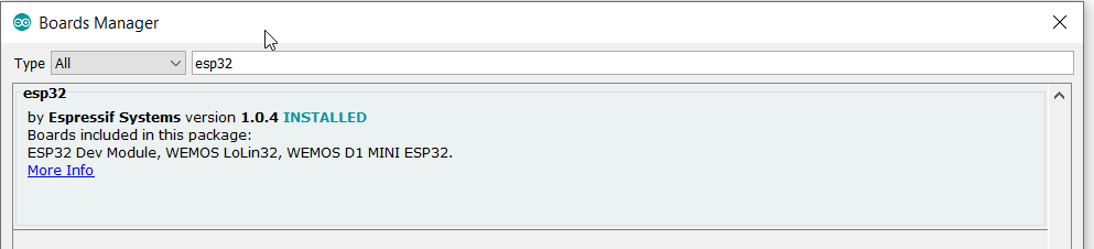
ESP32 board support should be added to the Arduino IDE.
WiFi module needs to be installed.
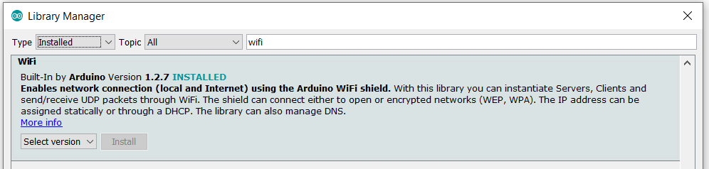
Note that there will be a compilation error if these modules are not installed properly!
If compilation is successful first module will be flashed and ready to be connected to hotspot.
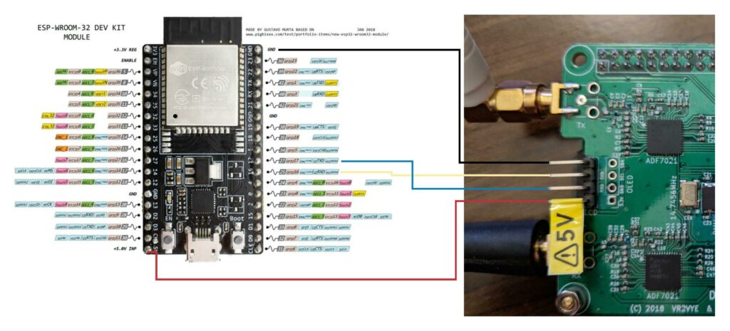
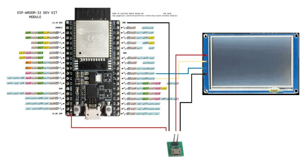
Wiring diagram provided below:
The display side
The following code should be placed in Arduino IDE:
#include <WiFi.h>

// debug log, set to 1 to enable
#define ENABLE_DEBUG_LOG 0

// wifi config
const char* ssid     = "espwifinetwork";
const char* password = "hdnHsncjdf7hs763Hbfjhse3A";

// ethernet config
const IPAddress local_IP(192, 168, 4, 2);
const IPAddress gateway(192, 168, 4, 1);
const IPAddress subnet(255, 255, 255, 0);

// rs-server config
const char * serverIP = "192.168.4.1";
const int serverPort = 1234;

// rs port config
const int baudrate = 9600;
const int rs_config = SERIAL_8N1;

// reading buffor config
#define BUFFER_SIZE 1024

// global objects
WiFiServer server;
byte buff[BUFFER_SIZE];
int size;

void debug_log(char* str) {
#if ENABLE_DEBUG_LOG == 1
   Serial.println(str);
#endif
}

void setup() {
#if ENABLE_DEBUG_LOG == 1
  // init log serial port
  Serial.begin(115200, rs_config);
#endif

// init rs port
   Serial2.begin(baudrate, rs_config);

// init wifi connection
if (!WiFi.config(local_IP, gateway, subnet)) {
       debug_log("Failed to configure network settings");
}

}

void loop() {

if (WiFi.status() != WL_CONNECTED) {
    WiFi.begin(ssid, password);
    while (WiFi.status() != WL_CONNECTED) {
           debug_log("connecting to WiFi network");
           delay(500);
    }
    #if ENABLE_DEBUG_LOG == 1
    Serial.println("connected to WiFi");
    Serial.println("IP adddr: ");
    Serial.println(WiFi.localIP());
    #endif
}

debug_log("Connecting to server");
//debug_log(serverIP);

// Use WiFiClient class to create TCP connections
WiFiClient client;

client.setTimeout(5);

if (!client.connect(serverIP, serverPort)) {
  debug_log("Connection failed.");
  debug_log("Waiting 5 seconds before retrying...");
  delay(5000);
  return;
}

while (client.connected()) {
  // read data from wifi client and send to serial
  if (client.available()) {
             size = client.available();
             size = (size >= BUFFER_SIZE ? BUFFER_SIZE : size);
             client.read(buff, size);
             Serial2.write(buff, size);
             Serial2.flush();
             #if ENABLE_DEBUG_LOG == 1
                Serial.println("WiFi->Serial");
             #endif
            }

  // read data from serial and send to wifi client
  if (Serial2.available()) {
             size = Serial2.available();
             size = (size >= BUFFER_SIZE ? BUFFER_SIZE : size);
             Serial2.readBytes(buff, size);
             client.write(buff, size);
             client.flush();
             #if ENABLE_DEBUG_LOG == 1
                Serial.println("Serial->WiFi");
             #endif
            }
}

debug_log("Closing connection.");
client.stop();

debug_log("Waiting 5 seconds before restarting...");
delay(5000);

}
The second module requires the same libraries. Nothing additional needed to be installed.
If compilation is successful the seccond module will be flashed and ready to be connected to display.
You need 6 wires to provide all required connectivity. It’s wise to use USB power adapter that goes together with Nextion display. It will provide 2 pins for “+” and 2 pins for “–“. The display can be powered via the ESP32 module but some noise from ESP32 might be visible on Nextion backlight.
Wiring schematics provided below:
Software configuration
The display should be flashed and tested before you connect the ESP32 module. Then proceed with the ESP32 modules connection only after Nextion display is working stable and has been wired to the hotspot.
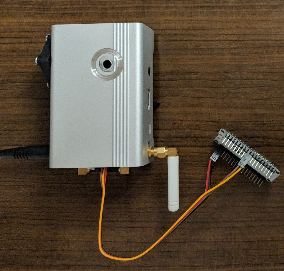
Final solution
The final solution for hotspot should look like this:
For display:
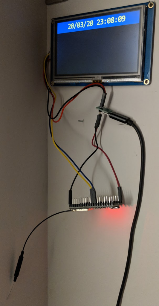
The modules are very small in size so the whole solution should fit in small case. Power consumption and heat is minor also.
Troubleshooting
Sometimes the display will not show information immediately after you connect the ESP32 modules.
You should follow these steps to minimize time for troubleshooting:
- power off then power on display side – sometimes the display module boots earlier than hotspot and gets into some loop
- disable then enable Nextion display in Pi-Star by setting MMDVM Display Type to None then back to Nextion
- enable ENABLE_DEBUG_LOG in in both sides, flash it into controllers, connect via USB and open Serial Monitor in Arduino IDE
- if you see 0,5-1,0 sec delay on Display (easy to catch with time display) that means WiFi signal level is low. This might be caused by long distance (with or w/o additional obstacles) or overcrowding of the 2.4 GHz spectrum part (this happens in my apartment complex every single evening)
Information sources list
- https://www.hackster.io/techbase_group/arduino-esp32-serial-port-to-tcp-converter-via-wifi-66d341
- https://atadiat.com/en/e-esp8266-esp32-wifi-serial-bridge-converter/
- https://hackaday.com/2015/09/18/transparent-esp8266-wifi-to-serial-bridge/
- https://github.com/AlphaLima/ESP32-Serial-Bridge